Previously, we have completed gpio input.
GPIO External Interrupt
1. Introduction
External interrupt is used to read the input pin asynchronously. It is used to read the input pin without polling the pin. The controller will execute the code only when the pin state changes.
Interrupt can be generated on the rising edge, falling edge, or both edges. It can also be generated on the low level or high level.
In this tutorial, we will see how to use external interrupt to detect rising edge signal on pin PA0 i.e. button press and use it to toggle led.
2. CubeMX Configuration
Open the
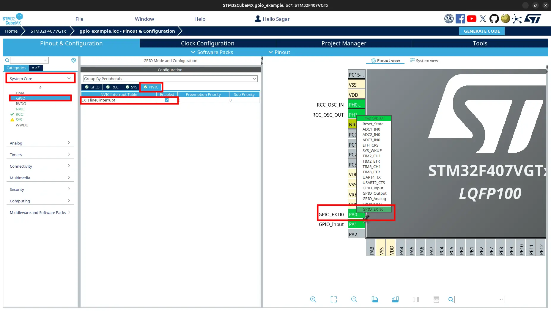
STM32CubeMX, update pinPA0toGPIO_EXTI0.From
Pinout & Configuration, go toGPIOand underNVICtab, enableEXTI line0 intereupt.
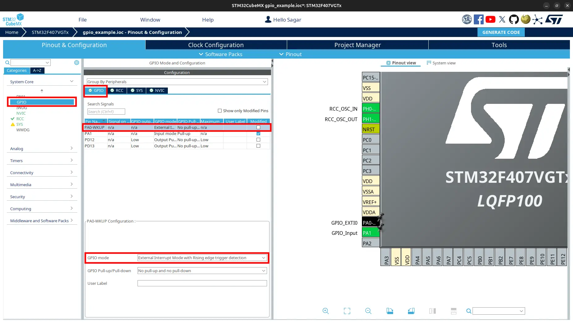
Under
GPIOtab, selectPA0-WKPlist. FromPA0-WKP Configuration, checkGPIO ModetoExternal Interrupt Mode with Rising edge trigger detection.
Generate code.
3. Code to Toggle LED using External Interrupt
Open project folder. Navigate to
Core/Src/main.c. AddHAL_GPIO_EXTI_Callbackfunction above themainfunction./* USER CODE BEGIN 0 */ void HAL_GPIO_EXTI_Callback(uint16_t GPIO_Pin) { // Toggle green led on pin PD12 when button is pressed. if (GPIO_Pin == GPIO_PIN_0) { HAL_GPIO_TogglePin(GPIOD, GPIO_PIN_12); } } /* USER CODE END 0 */
Note
HAL_GPIO_EXTI_Callback(uint16_t GPIO_Pin) is a callback function which is called when the external interrupt is generated. It is used to handle the interrupt. It is weakly defined inside HAL Driver.
Update the
whileblock of themainfunction to show processor can do other job simultaneously./* Infinite loop */ /* USER CODE BEGIN WHILE */ while (1) { // Toggle Orage Led Continously HAL_GPIO_TogglePin(GPIOD, GPIO_PIN_13); HAL_Delay(100); /* USER CODE END WHILE */ /* USER CODE BEGIN 3 */ } /* USER CODE END 3 */
Build and flash the code.
4. Observation
Orage led on pin
PD13blinking continuously.Pressing the user button on pin
PA0, the green led on pinPD12toggles.
Note
It is possible that pressing the button toggles the led multiple times. This is because the button is mechanical and it bounces. We will see how to debounce the button in the later tutorial.