This is continued from gpio output.
GPIO Input
1. Logic
For 3V3 microcontrollers:
Logic 1 above 1.88V.
Login 0 below 1.23V.
Most of them are 5V tolerant.
For 5V microcontrollers:
Logic 1 above 3V
Logic 0 below 1.5V
When VCC is appled to input pin, the input state will be high. And when GND is applied to input pin, the input state will be low. But if input pin is disconnected, the input is on floating state and it is hard to predict. So to remove such ambiguity pull-up or pull-down resistors are connected to input pin.
Microcontrollers have internal pull-up/pull-down resistors which can be connectd by programming. We also can connect external pull-up/pull-down resistors. Typical value for pull-up/pull-down resistors are 4.7K and 10K.
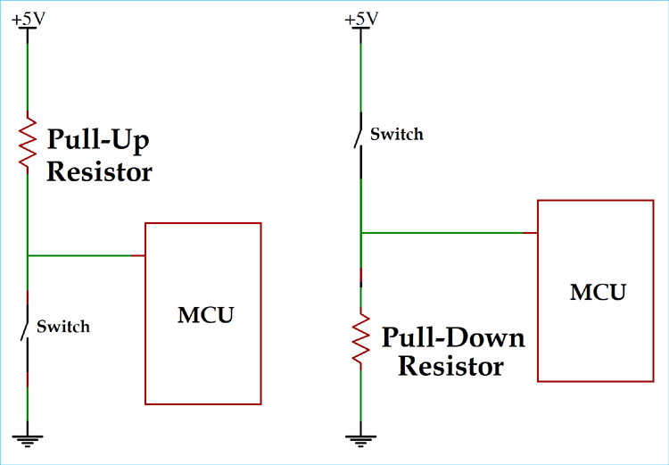
Pull-up resistor connects the input pin to VCC and pull-down resistor connects the input pin to GND. When input pin is not connected, pull-up resistor connects the input pin to VCC and pull-down resistor connects the input pin to GND. So, the input state will be high and low respectively.
For Open Drain output, pull-up resistor is used. For Open Collector output, pull-down resistor is used. Signals with pull-ups tend to be less sensitive to noise in noisy environments (e.g., industrial environments) because they are biased toward the high state.
2. CubeMX Configuration
To read the input from the GPIO pin, we need to configure the pin as input. Open STM32CubeMX to configure the pin as input. Discovery board has a user button on PA0 pin. To know about this, open STM32F407G-DISC1 from board selector of STM32CubeMX in default mode or see schematic of Discovery Board. Select pin PA1 as GPIO_Input. Also select pin PA1 as GPIO_Input.
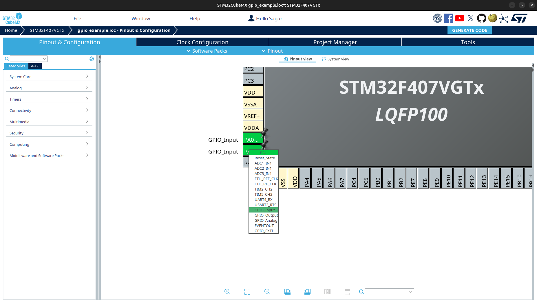
The pin PA0 is already pulled down on the board, so we do not need to do anything with pin PA0 but for pin PA1, we will pull it up using internal pull-up resistor.
From CubeMX
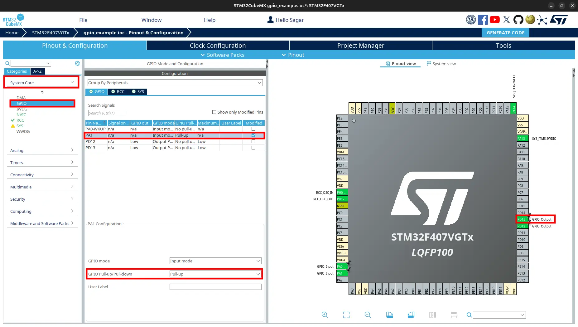
Pin & Configuration, navigate toSystem Core > GPIO.Inside
GPIO Mode and ConfigurationunderGPIOtab, selectPA1from the list.PA1 Configurationwill be expaned.From
PA1 Configuration, changeGPIO Pull-up/Pull-downtoPull-up.Also set pin
PD13toGPIO_Output.
Now generate code.
3. Code to Check PinState
Open project folder. Navigate to Core/Src/main.c. Update the while block.
/* Infinite loop */
  /* USER CODE BEGIN WHILE */
  while (1)
  {
    // Check pin PA0
    if (HAL_GPIO_ReadPin(GPIOA, GPIO_PIN_0) == GPIO_PIN_SET)
    {
      // turn on green led on pin PD12.
      HAL_GPIO_WritePin(GPIOD, GPIO_PIN_12, GPIO_PIN_SET);
    }
    else
    {
      // turn off green led on pin PD12
      HAL_GPIO_WritePin(GPIOD, GPIO_PIN_12, GPIO_PIN_RESET);
    }

    // Check pin PA1
    if (HAL_GPIO_ReadPin(GPIOA, GPIO_PIN_1) == GPIO_PIN_SET)
    {
      // turn on orange led on pin PA13
      HAL_GPIO_WritePin(GPIOD, GPIO_PIN_13, GPIO_PIN_RESET);
    }
    else
    {
      // turn off orange led on pin PA13
      HAL_GPIO_WritePin(GPIOD, GPIO_PIN_13, GPIO_PIN_SET);
    }
    /* USER CODE END WHILE */

    /* USER CODE BEGIN 3 */
  }
  /* USER CODE END 3 */
It is easy to understand this code.
If pin
PA0is set high i.e. user button is pressed, green led turns on else off.If pin
PA1is set high i.e. pinPA1connected to VCC, orange led turns on else off.
Pin PA0 is pulled low on the board, so not pressing user buttons connects pin PA0 to GND. Pin PA1 is pulled high, so not connecting anything to pin PA1 sets pin PA1 high.
Build and flash the code to controller.
4. Observation
You can use a jumper to connect pin PA1 to connect to GND or 3V3.
Green led turns on only if user button is pressed.
Orange led turns off only if pin
PA1is connected to GND.
Next, we will see how to use external interrupt to read the input pin.
References
References are from STM32 HAL Driver documentation.
-
GPIO_PinState HAL_GPIO_ReadPin(GPIO_TypeDef *GPIOx, uint16_t GPIO_Pin)
Reads the specified input port pin.
- Parameters:
GPIOx (GPIO_TypeDef*) – Specifies the GPIO peripheral. - For STM32F429X devices: A..K - For STM32F40XX and STM32F427X devices: A..I
GPIO_Pin (uint16_t) – Specifies the port bit to read. This parameter can be
GPIO_PIN_xwhere x can be (0..15).
- Returns:
The input port pin value (GPIO_PIN_SET or GPIO_PIN_RESET).
- Return type:
GPIO_PinState