GPIO Output
1. CubeMX Configuration
Open STM32CubeMx. Generate basic code by assing osccillator pins, serial wire pins, configuring clock and project detail. Follow the generate_basic_code with:
microcontroller:
stm32f407vgt6or board:STM32F407VG-DISC1project name:
gpio_exampleToolchain/IDE:
Makefile
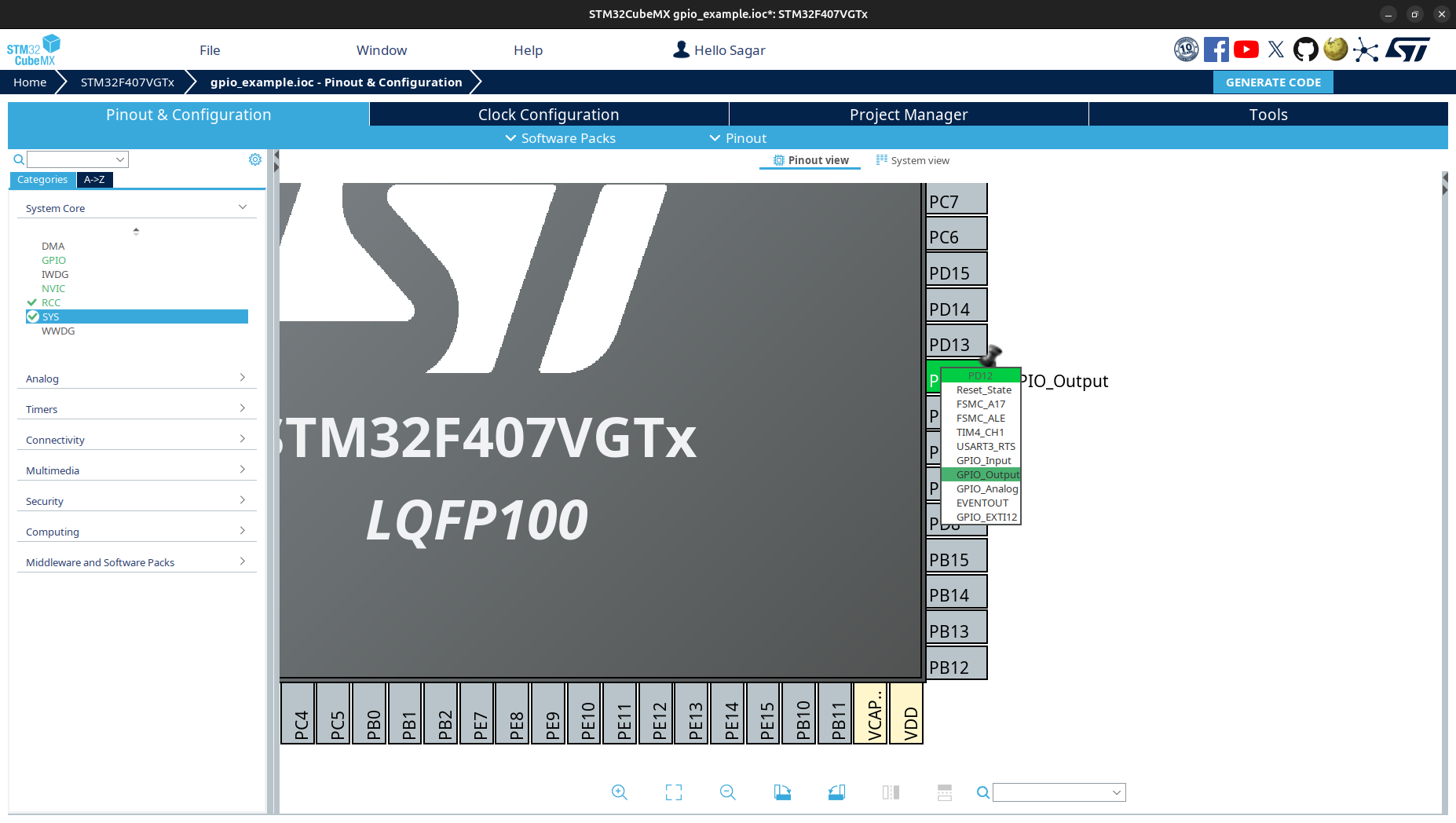
STM32 Discovery board have leds on pins PD12, PD13, PD14 and PD15. Move to STM32CubeMX Pinout and Congiguration. Click PD12 and select GPIO-Output. For Bluepill, led pin is on PA13. Generate code.
2. Understanding the Project Structure
Well, you have generated the code. Now, let’s understand the project structure.
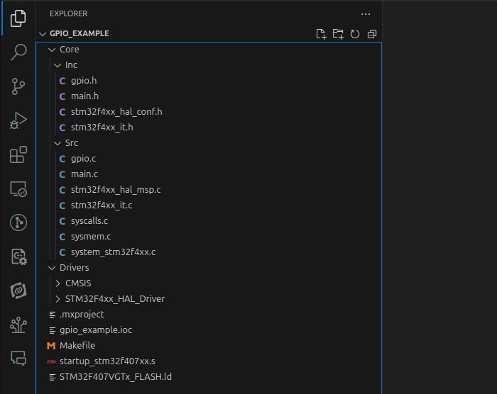
Core: Contains the startup main file, peripheral files and other system configuration files. -Inc: Contains the header files. -Src: Contains the source files.Drivers: Contains the HAL library. -CMSIS: Contains the Cortex Microcontroller Software Interface Standard. -STM32F4xx_HAL_Driver: Contains the HAL library.gpio_example.ioc: The project file. It conts configuration of the microcontroller used for STM32CubeMX.Makefile: The makefile to build the project.startup_stm32f407xx.s: The startup file. It contains the vector table and the reset handler.STM32F407VGTx_FLASH.ld: The linker script file. It contains the memory layout of the microcontroller.
We mostly expend time on Core. Since you have generated the code for GPIO, you can see gpio.h and gpio.c.
3. Code to Blink LED
Open project folder. Navigate to Core/Src/main.c. You can see codes with lots of comments. These comments are special which allow separate user code and code generated by CubeMX.
Danger
You must write you code inside comment block. Begin and End are specified by /* USER CODE BEGIN x */ and /* USER CODE END x */. Here x is the number. If you write outside this block, your code will be lost when you regenerate the code using CubeMX.
To make LED blink, move to while block of main(). You can use the following code:
/* Infinite loop */
/* USER CODE BEGIN WHILE */
while (1)
{
  HAL_GPIO_WritePin(GPIOD, GPIO_PIN_12, GPIO_PIN_SET);
  HAL_Delay(1000);
  HAL_GPIO_WritePin(GPIOD, GPIO_PIN_12, GPIO_PIN_RESET);
  HAL_Delay(1000);
  /* USER CODE END WHILE */

  /* USER CODE BEGIN 3 */
}
/* USER CODE END 3 */
Let’s understand the code:
HAL_GPIO_WritePin(GPIOD, GPIO_PIN_12, GPIO_PIN_SET): Sets the pinPD12high. Green led turns on.HAL_Delay(1000): Delays the execution for 1000ms. Green led keeps turning on for 1s.HAL_GPIO_WritePin(GPIOD, GPIO_PIN_12, GPIO_PIN_RESET): Sets the pinPD12low. Green led turns off.HAL_Delay(1000): Delays the execution for 1000ms. Green leed keeps turning off for 1s.
Therefore, the LED will blink with 1s delay.
You can also use HAL_GPIO_TogglePin(GPIOD, GPIO_PIN_12) to toggle the pin state.
Note
`Bluepill` board have led on pin PC13 which is active low. It means, on GPIO_PIN_SET led will be off and on GPIO_PIN_RESET led will be on.
4. Build and Flash
We need to add few line of code in the makefile to flash the code. Open Makefile and add the following lines at the bottom:
#######################################
# flash
#######################################
flash: $(BUILD_DIR)/$(TARGET).bin
     st-flash --reset write $(BUILD_DIR)/$(TARGET).bin 0x8000000
Now, build and flash the code.
make -j
make flash
This code only works with ST-Link. If you are using JLink, see build_setup and flash binary.
We will continue it for gpio input.
5. Observation
See LED blinking every second. Change delay time and enjoy.
References
References are from STM32 HAL Driver documentation.
- HAL_GPIO_WritePin(GPIOx, GPIO_Pin, PinState)
Sets or clears the selected data port bit.
Note: This function uses the GPIOx_BSRR register to allow atomic read/modify accesses. There is no risk of an IRQ occurring between the read and modify access.
- Parameters:
GPIOx (GPIO_TypeDef) – GPIO peripheral where x can be: - (A..K) for STM32F429X devices - (A..I) for STM32F40XX and STM32F427X devices
GPIO_Pin (uint16_t) – Specifies the port bit to be written. Can be one of the following: -
GPIO_PIN_0throughGPIO_PIN_15PinState (GPIO_PinState) – Specifies the value to be written to the selected bit. Can be one of the following: -
GPIO_PIN_RESET: Clears the port pin -GPIO_PIN_SET: Sets the port pin
- Returns:
None
- HAL_GPIO_TogglePin(GPIOx, GPIO_Pin)
Toggles the state of the specified GPIO pins.
- Parameters:
GPIOx (GPIO_TypeDef*) – GPIO peripheral where x can be: - (A..K) for STM32F429X devices - (A..I) for STM32F40XX and STM32F427X devices.
GPIO_Pin (uint16_t) – Specifies the pins to be toggled. This parameter can be a combination of GPIO_PIN_x values where x can range from 0 to 15.
- Returns:
None
- Return type:
None
- HAL_Delay(Delay)
Provides a minimum delay (in milliseconds) based on a variable that is incremented regularly.
Note 1: In the default implementation, the SysTick timer is used as the time base. It generates interrupts at regular time intervals, where uwTick is incremented.
Note 2: This function is declared as __weak to allow overriding by user implementations in other files.
- Parameters:
Delay (uint32_t) – Specifies the delay time length, in milliseconds.
- Returns:
None
- Return type:
None