Frequency counter
1. Introduction
The frequency counter counts the number of cycles of an input signal over a specific time period and calculates the frequency based on the count. It is used to measure the frequency of periodic signals like square waves, sine waves, or pulses. The frequency counter can be implemented using timers in microcontrollers.
2. CubeMX Configuration
Open CubeMX and generate basic code with:
microcontroller:
stm32f407vgt6or board:STM32F407VG-DISC1project name:
frequency_counterToolchain/IDE:
Makefile
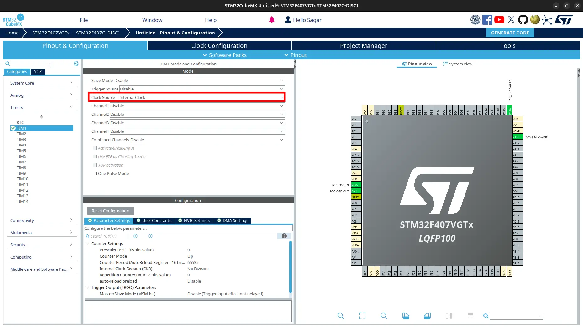
Go to
Pinout and Congiguration > Timers > TIM1and select Clock Source:Internal Clock.
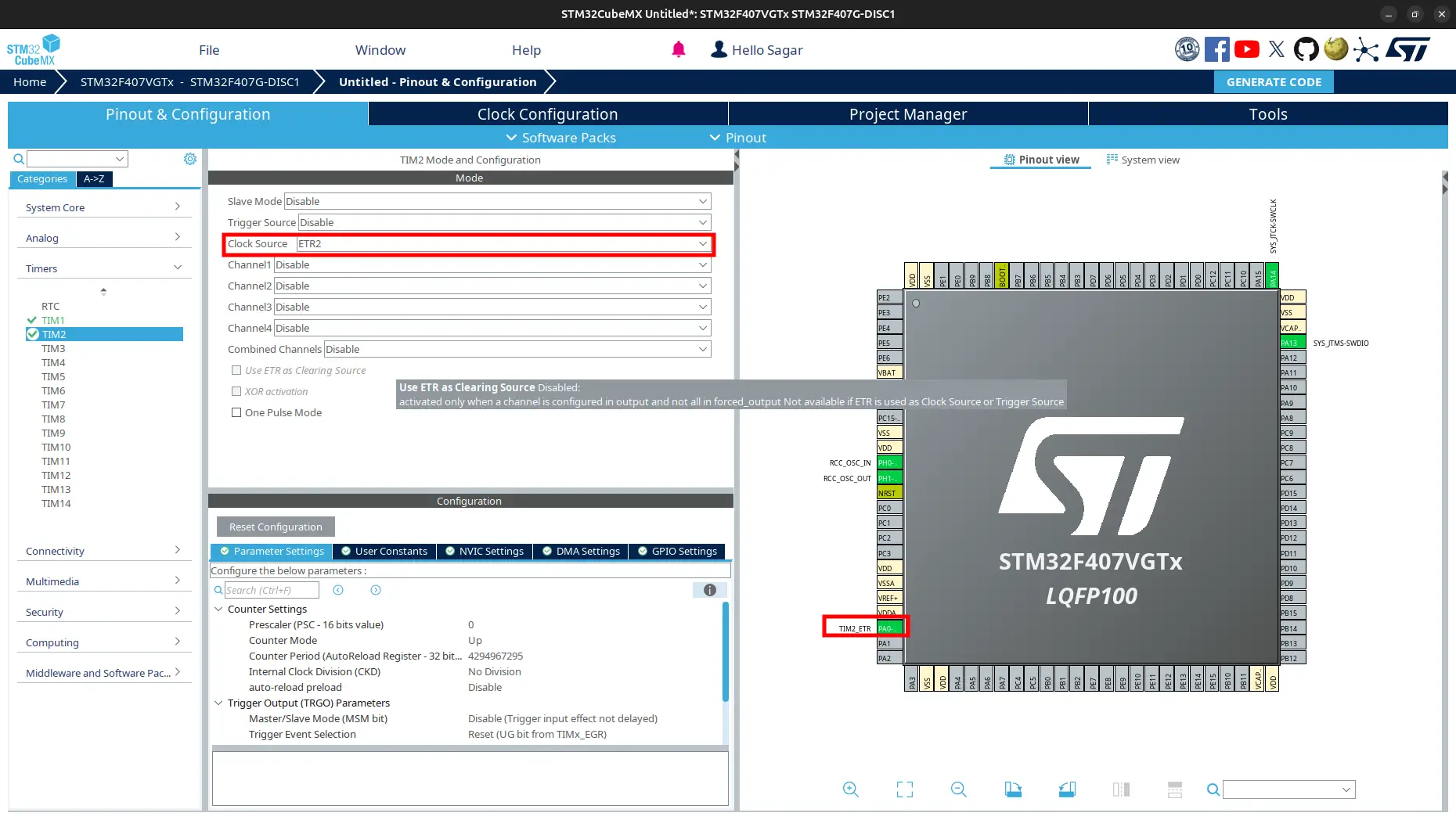
Go to
TIM2and select Clock Source:ETR2.
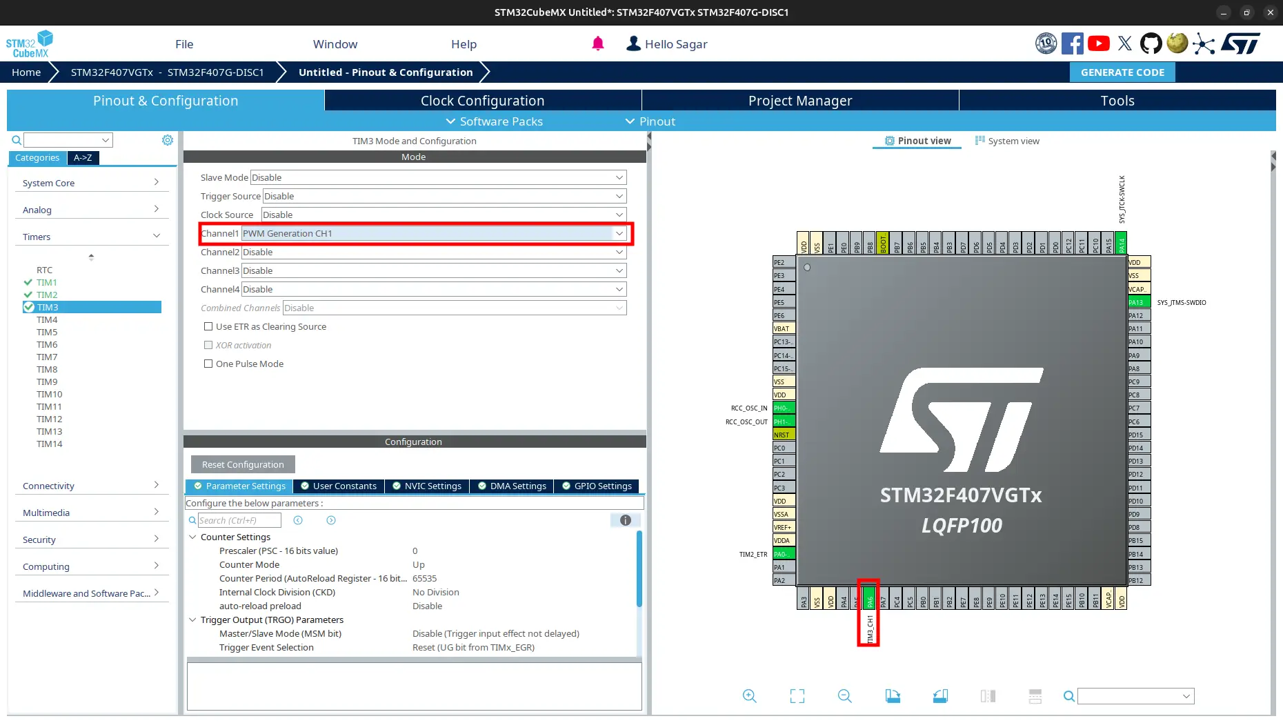
Go to
TIM3and select Channel1:PWM Generation CH1.
Generate Code.
3. Code to Get Frequency
Navigate to
Core > Srcand openmain.c.Include header file.
/* USER CODE BEGIN Includes */
#include <stdio.h>
/* USER CODE END Includes */
/* USER CODE BEGIN Includes */
#include <stdio.h>
#include "usbd_cdc_if.h"
/* USER CODE END Includes */
Overwrite definition of
_writeas:/* USER CODE BEGIN 0 */ int _write(int file, char *data, int len) { for (int i = 0; i < len; ++i) { ITM_SendChar(data[i]); } return len; } /* USER CODE END 0 */
/* USER CODE BEGIN 0 */
int _write(int file, char *data, int len)
{
  CDC_Transmit_FS((uint8_t*)data, (uint16_t)len);
  return len;
}
/* USER CODE END 0 */
Create variable to store timer-1 period ellapsed count.
/* USER CODE BEGIN PV */
uint32_t htim1PeriodEllapsedCount = 0;
/* USER CODE END PV */
Increment the
htim1PeriodEllapsedCountinHAL_TIM_PeriodElapsedCallback. Also add function to get microtick./* USER CODE BEGIN 0 */ // ... // ... void HAL_TIM_PeriodElapsedCallback(TIM_HandleTypeDef *htim) { if (htim->Instance == htim1.Instance) { htim1PeriodEllapsedCount++; } } uint64_t GetMicros() { return (uint64_t)htim1PeriodEllapsedCount * htim1.Instance->ARR + (uint64_t)htim1.Instance->CNT; } /* USER CODE END 0 */
Add timer init code for
TIM1,TIM2andTIM3./* USER CODE BEGIN 2 */ HAL_TIM_Base_Start_IT(&htim1); HAL_TIM_Base_Start(&htim2); HAL_TIM_PWM_Start(&htim3, TIM_CHANNEL_1); /* USER CODE END 2 */
Add code to get frequency of input signal.
/* Infinite loop */
/* USER CODE BEGIN WHILE */
uint64_t startTick;
uint64_t endTick;
uint32_t count;
double freq;

htim3.Instance->CCR1 = (uint32_t)(0.5f * htim3.Instance->ARR);

while (1)
{
  startTick = GetMicros(); // using microsecond to get precise frequency
  htim2.Instance->CNT = 0;
  HAL_Delay(100); // 100ms sampling time
  count = htim2.Instance->CNT;
  uint64_t endTick = GetMicros();

  freq = (double)count / ((endTick - startTick) / 1000000.0);
  printf("Frequency: %f Hz\n", (float)freq);
  /* USER CODE END WHILE */

  /* USER CODE BEGIN 3 */
}
/* USER CODE END 3 */
Build and flash the code.
Warning
To print floating point, make sure you have added -u _printf_float to LDFLAGS in Makefile. Otherwise it does not get printed.
4. View Output
Connect
TIM3_CH1pin toTIM2_ETRpin.Open
STM32CubeProgrammerand view output onSWV. If you used USB, see on terminal or serial monitor.Now, change the frequency of PWM signal to 50Hz and again view the output. To know how change PWM frequency, see PWM tutorial.