PWM
1. Introduction
Pulse Width Modulation (PWM) is a technique used in embedded systems to generate analog-like signals using digital means. It works by varying the width of pulses (the “on” time) in a periodic waveform to encode information or control power delivered to a load.
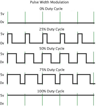
The amplitude of PWM is equal to VDD of microcontroller; i.e. for arduino controller, it is 5V; for stm32 controllers, it is 3.3V.
The average output of a PWM signal is given by \(V_{avg} = \frac{\text{Pulse Width}}{\text{Time Period}} \cdot V_{dd}\).
2. CubeMX Configuration
Open CubeMX and generate basic code with:
microcontroller:
stm32f407vgt6or board:STM32F407VG-DISC1project name:
pwm_testToolchain/IDE:
Makefile
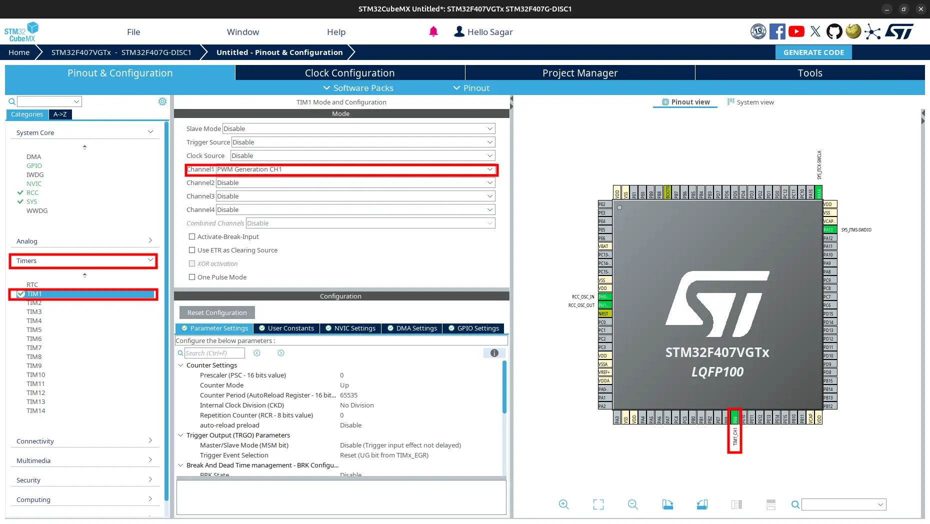
Go to
Pinout and Congiguration > Timers > TIM1. SelectPWM Generation CH1for CHANNEL1.Generate code.
3. Code to Change Duty Cycle
Navigate to
Core > Srcand openmain.c.Add to the
main()as:int main(void) { /* USER CODE BEGIN 1 */ /* USER CODE END 1 */ /* MCU Configuration--------------------------------------------------------*/ /* Reset of all peripherals, Initializes the Flash interface and the Systick. */ HAL_Init(); /* USER CODE BEGIN Init */ /* USER CODE END Init */ /* Configure the system clock */ SystemClock_Config(); /* USER CODE BEGIN SysInit */ /* USER CODE END SysInit */ /* Initialize all configured peripherals */ MX_GPIO_Init(); MX_TIM1_Init(); /* USER CODE BEGIN 2 */ HAL_TIM_PWM_Start(&htim1, TIM_CHANNEL_1); /* USER CODE END 2 */ /* Infinite loop */ /* USER CODE BEGIN WHILE */ while (1) { float duty = 0.5f; htim1.Instance->CCR1 = (uint32_t)(duty * htim1.Instance->ARR); // You can also use the HAL function to set the duty cycle: // __HAL_TIM_SET_COMPARE(&htim1, TIM_CHANNEL_1, (uint32_t)(duty * htim1.Instance->ARR)); /* USER CODE END WHILE */ /* USER CODE BEGIN 3 */ } /* USER CODE END 3 */
4. Test Output
Connect the
TIM1_CH1pin to positive of anLEDand negative terminal toGND.Change the value of
dutyto0,0.1f,0.8fand1.0f, and observe the brightness of LED.Observe the output on Oscilloscope.
Assignment: Control the speed of a motor using any motor driver available.
Caution
If PWM pin is pulled up, it sends logic high at reset. So make sure not to use pulled up pins for PWM to control motors. But you can use the pulled up pins to control servo motors. STM32F407VG-DISC1 board have many pulled up pins as it contains many peripherals. You can check them using multimeter under reset. To hold the reset, use STM32CubeProgrammer. If you connect it and open SWV, it is under reset uintill you press START.
5. Changing the Frequency of PWM
The PWM frequency on an STM32 microcontroller can be calculated using the formula:
Use the following calculator to calculate the PWM frequency.
Increasing PSC and ARR decreases PWM frequency, and decreasing them increases PWM frequency. There is another point to note that decreasing ARR also decreases resolution of duty cycle. To change the duty cycle, you need to set the value of CCR register. The formula to calculate the duty cycle is:
This is useful for applications like servo control, where the pulse width determines the position.
The resolution of pulse width is the change in pulse width that can be achieved by changing the value of CCR register by 1. It is calculated as:
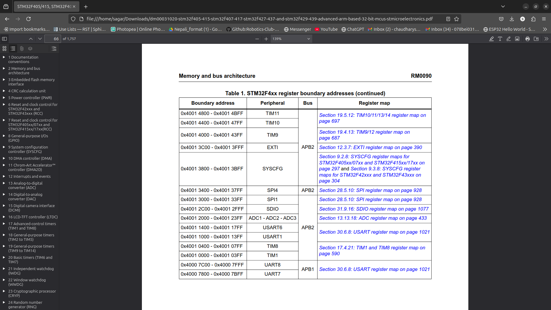
To determine the frequency of timer, first you need to find out the APB timer clock in the reference mannual of the microcontroller.
On
STM32CubeMX, hover the cursor onTimers.Click the
details and documentationand thenReference mannual. Or click reference mannual link.You can find the APB number under Memory and bus architecture.
Now on STM32CubeMx, go to Clock Configuration tab and check the target APB clock frequency.
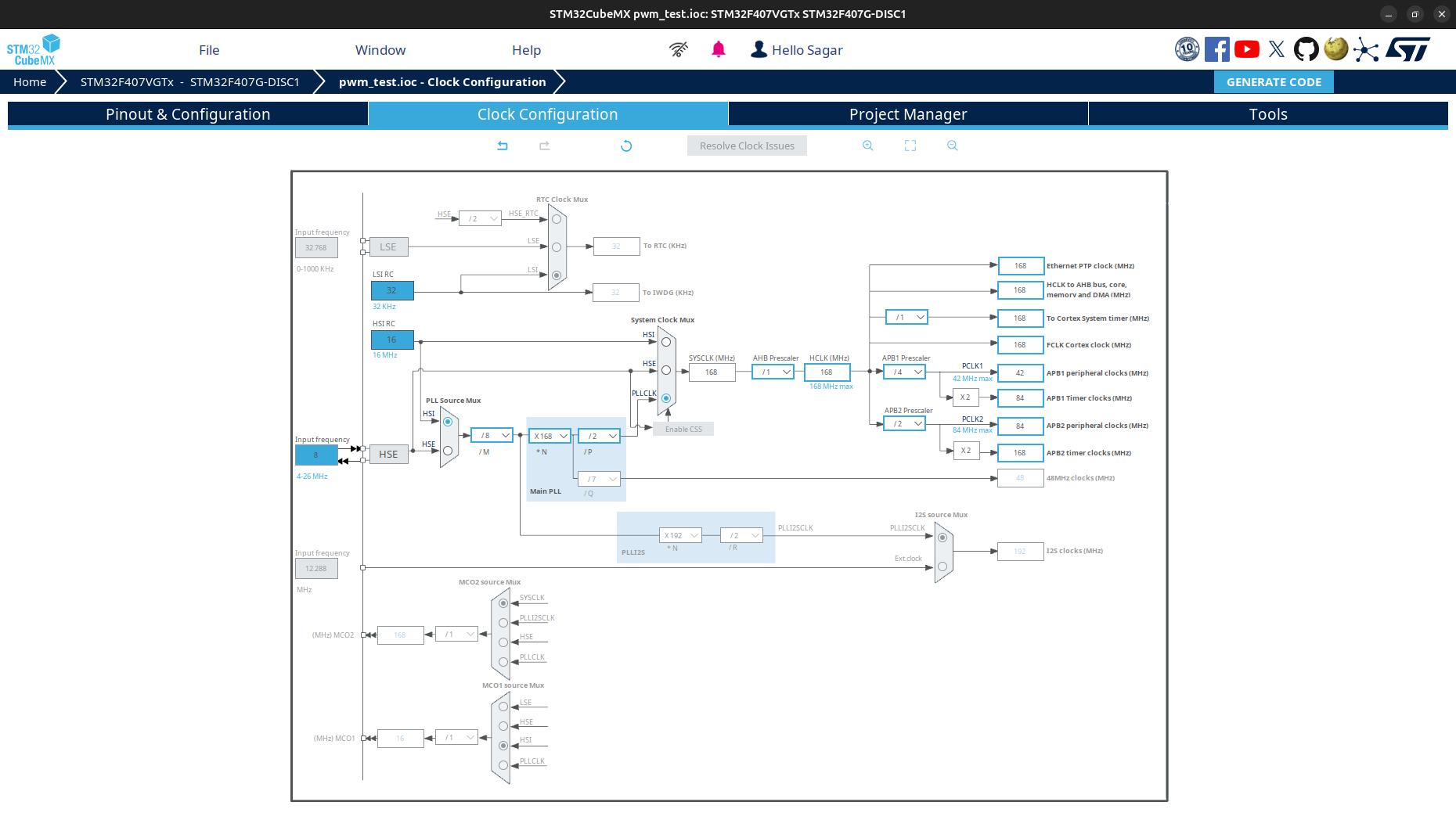
For this case, for TIM1, the APB2 timer clock is 168MHz.
Suppose, we want the PWM frequency to be 50Hz. For this we need to calculate and adjust the ARR and PSC values.
If \(f_{\text{TIM}}\) is 168MHz, \(\text{PSC}\) is 167 and \(f_{\text{PWM}}\) is 50Hz, then \(\text{ARR}\) will be:
Use the following calculator to calculate the ARR value.
Note
We chose \(\text{PSC}\) as 167 because the \(f_{\text{TIM}}\) is 168MHz. So \(\frac{f_{\text{TIM}}}{\text{PSC} + 1}\) will be 1MHz for easy calculation.
Warning
To get good response from DC motors, higher PWM frequency is better but motordriver should be capable to handle that frequency. Lower frequency can make tunning sound from DC motors. I used 8KHz pwm frequency for planetary gear motors.
Go to Pinout & Configuration > Timers > TIM1 > Parameter Settings and set the ARR value to 19999 and PSC value to 167.
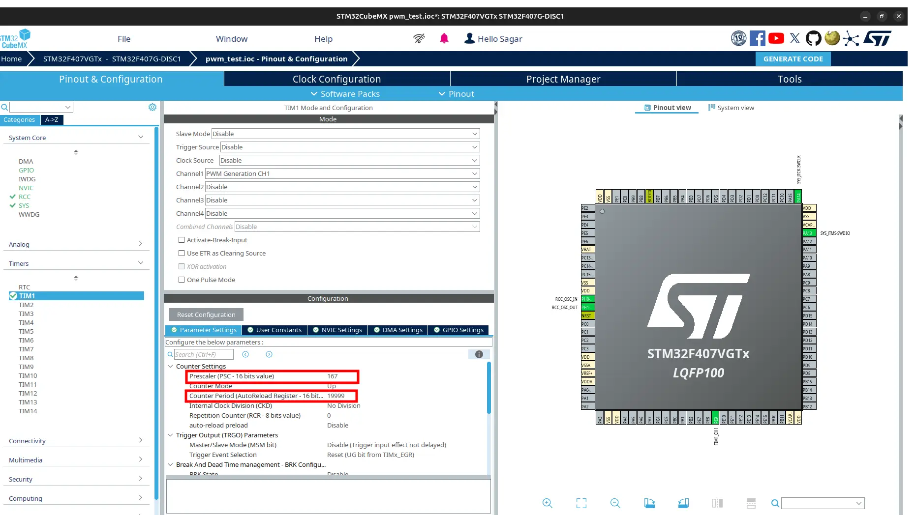
Generate the code, change the duty cycle between 0% and 100%. Observe the output frequency on the oscilloscope.
Assignment: Control the angle of a servo motor.
Hint
For \(f_{\text{PWM}} = 50\,\text{Hz}\), time period \(T = 20\,\text{ms}\). And \(1\,\text{ms} \equiv 0^\circ\) and \(2\,\text{ms} \equiv 180^\circ\).
const float timePeriod = 20.0f; // in ms
float duty = map<float>(angle, 0, 180, 1, 2); // in ms

htim1.Instance->CCR1 = (uint32_t)(htim1.Instance->ARR * duty / timePeriod);
Tip
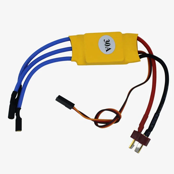
ESC
To control Brushless DC Motor (BLDC), Electronic Speed Controller (ESC) is used that accepts RC Servo PWM signal. Servo can run just after power on, but ESC does not allow you run just after power on. There are calibration and arming process just after power on indicated by beep sound. Calibration is to set the full and low throttle for control and arming is for safety purpose that does not allow to run accidentally. Generally calibrate zero throttle 1ms and high throttle 2ms at 50Hz.
To calibrate, use full throttle (2ms pulse) for 2 seconds and then use zero throttle (1ms pulse) for 2 seconds. You don’t need to calibrate it again until you change the ESC or BLDC.
To arm, use zero throttle for 2 seconds. You need to arm every time after power on otherwise ESC wiil make rapid beeping sound to alert.
For more concept, you can watch this video: